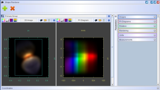
With the image parameter tab on the Render Module you control the extend of your image on the sky. It also allows you to set the image resolution, i.e. the FWHM of the gaussian point spread function, as well as the spectrograph slit parameters. All units are physical units like arcsec, meters, parsec, etc. How the physical units of the Render Module relate to the generic units of the 3D Module is set in the Units Setup of the Render Module.
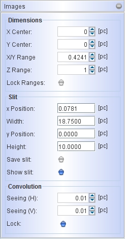
Beginning with the Dimensions the X and Y Center is set. This is espcially useful when you compare your model with an observed image that is not exactly centered. The extent on the sky is set with the X/Y Range. Note that the range indicates the extent from the center to either side, i.e. the full size is twice the nominal range. The Z Range is by default locked to the X/Y Range, by may be set independent of those by disabling the Lock Ranges button. Having them independent is sometimes useful when working in a mesh rendering mode and an object is much longer along the line of sight that in the plane of the sky.
Since the internal volumetric cube has the same number of elements (voxels) in all directions, this implies that the spatial resolution is lower if the range in Z is larger than in X/Y. IF the Z Range is too small to fit the object, the regions outside the cube will be excluded from the rending. Beware of this fact, if unexpected results appear. This can be solved by looking at your object from a perpendicular camera angle and measuring the size. Then adjust the Z Range and then go back to the original viewing angle.
With the spectrograph slit the region that is selected from the image to be included in the calculation of spectral information like the position-velocity diagrams or spectral plots. The region is marked with a green rectangle on the image. To disable the display of the slit, uncheck the Show Slit button. The position, width and height can be set independently and are in physical units (the current units are displayed in brackets to the right of the number fields).
Using the slit size and position appropriately one can either cover the full object, a narrow slit with full vertical extent or only a small region setting the dimensions as a small rectangle and placing it at any position on the image. The slit marking can be included in the saved images when checking the Save slit button.
Seeing and image convolution:
The image resolution is set in the Convolution section of the image parameters. You can separately set horizontal and vertical FWHM of the gaussian convolution kernel (labeled Seeing). By default the values are set equal and locked, such that changing one also changes de other. However, in some applications, e.g. radio interferometry, the point-spread function, or "beam" may be elliptical, such that the Seeing values will be set differently.
Currently, the orientation of an elliptical beam can not be rotated arbitrarily in Shape, such that, If the direction of the elongated beam is not up-down or left-right, the orientation of the observation should be changed such that it is up-down or left-right to be compared directly with the Shape model.